The initial lead was a YouTube Video by Adaptive Design. The video explains the mathematics, so it will not be repeated here. It also mentioned the existence of some pipelined HDL code, but as its a video its not available, so I have recreated and generalised it here.
Source Material
In short, the bit position of the first bit set to 1 directly gives you the integer part of the Log2() result. A fractional approximation can be added for each additional bit below the first bit. A lookup table can optionally be used to add each fractional bit's contribution. Watch the video for the detail. Note the code below does not employ the 4-bit OR gates used in the video.
VHDL Code
library ieee;
  use ieee.std_logic_1164.all;
  use ieee.fixed_pkg.all;
library local;

entity quick_log2 is
  generic(
    data_width_g : positive := 16;
    frac_width_g : positive := 4;
    use_lut_g    : boolean  := true -- true more accurate, false better timing
  );
  port (
    clk    : in  std_logic;
    linear : in  std_logic_vector(data_width_g-1 downto 0);
    log    : out ufixed(local.math_pkg.ceil_log(data_width_g, 2)-1 downto -frac_width_g)
  );
end entity;


library ieee;
  use ieee.numeric_std_unsigned.all;

architecture rtl of quick_log2 is

  type lut_type is array (0 to 2**frac_width_g-1) of std_logic_vector(frac_width_g-1 downto 0);

  function log2_lut return lut_type is
    use ieee.math_real.log2;
    use ieee.math_real.round;
    variable ret : lut_type;
  begin
    for i in lut_type'range loop
      ret(i) := to_slv(
        integer(round(real(2**frac_width_g) * log2(real(1.0 + real(i)/real(2**frac_width_g))))),
        ret(i)'length
      );
    end loop;
    return ret;
  end function;

  constant log2_frac_lut_c : lut_type := log2_lut;

  function get_msb_pos(val : std_logic_vector) return integer is
  begin
    for i in val'range loop
      if val(i) = '1' then
        return i;
      end if;
    end loop;
    return 0;
  end function;

begin

  process(clk)

    variable msb_idx_v  : integer range 0 to data_width_g-1;
    variable mantissa_v : std_logic_vector(frac_width_g-1 downto 0);
    variable fraction_v : std_logic_vector(frac_width_g-1 downto 0);

  begin
    if rising_edge(clk) then
      -- Find MSB position (Integer part)
      msb_idx_v := get_msb_pos(linear);

      -- Extract fractional bits directly following the leading '1'
      -- Handles boundary cases where remaining bits are fewer than frac_width_g
      mantissa_v := (others => '0');
      for j in 0 to frac_width_g-1 loop
        if (msb_idx_v - 1 - j) >= 0 then
          mantissa_v(frac_width_g - 1 - j) := linear(msb_idx_v - 1 - j);
        else
          mantissa_v(frac_width_g - 1 - j) := '0';
        end if;
      end loop;

      -- Look up fractional bits
      if use_lut_g then
        -- Maximum error = 0.1074 for 4 fractional bits
        fraction_v := log2_frac_lut_c(to_integer(mantissa_v));
      else
        -- Really simple, note the log2_frac_lut_c is nearly output = input
        -- Maximum error = 0.1485 for 4 fractional bits
        fraction_v := mantissa_v;
      end if;

      -- Combined 8-bit result in unsigned fixed point Qm.f format where:
      --  * m = log2(data_width_g)-1
      --  * f = frac_width_g
      log <= to_ufixed(to_slv(msb_idx_v, 4) & fraction_v, log);
    end if;
  end process;

end architecture;
If you need a simpler implementation to work with older tools, the LUT can be hard coded, the 4-bit fractional LUT is as follows:
  -- Mathematically accurate log2 LUT for a 4-bit mantissa
  constant log2_frac_lut_c : lut_type := (
    X"0", X"1", X"3", X"4", X"5", X"6", X"7", X"8",
    X"9", X"A", X"B", X"C", X"D", X"E", X"F", X"F"
  );
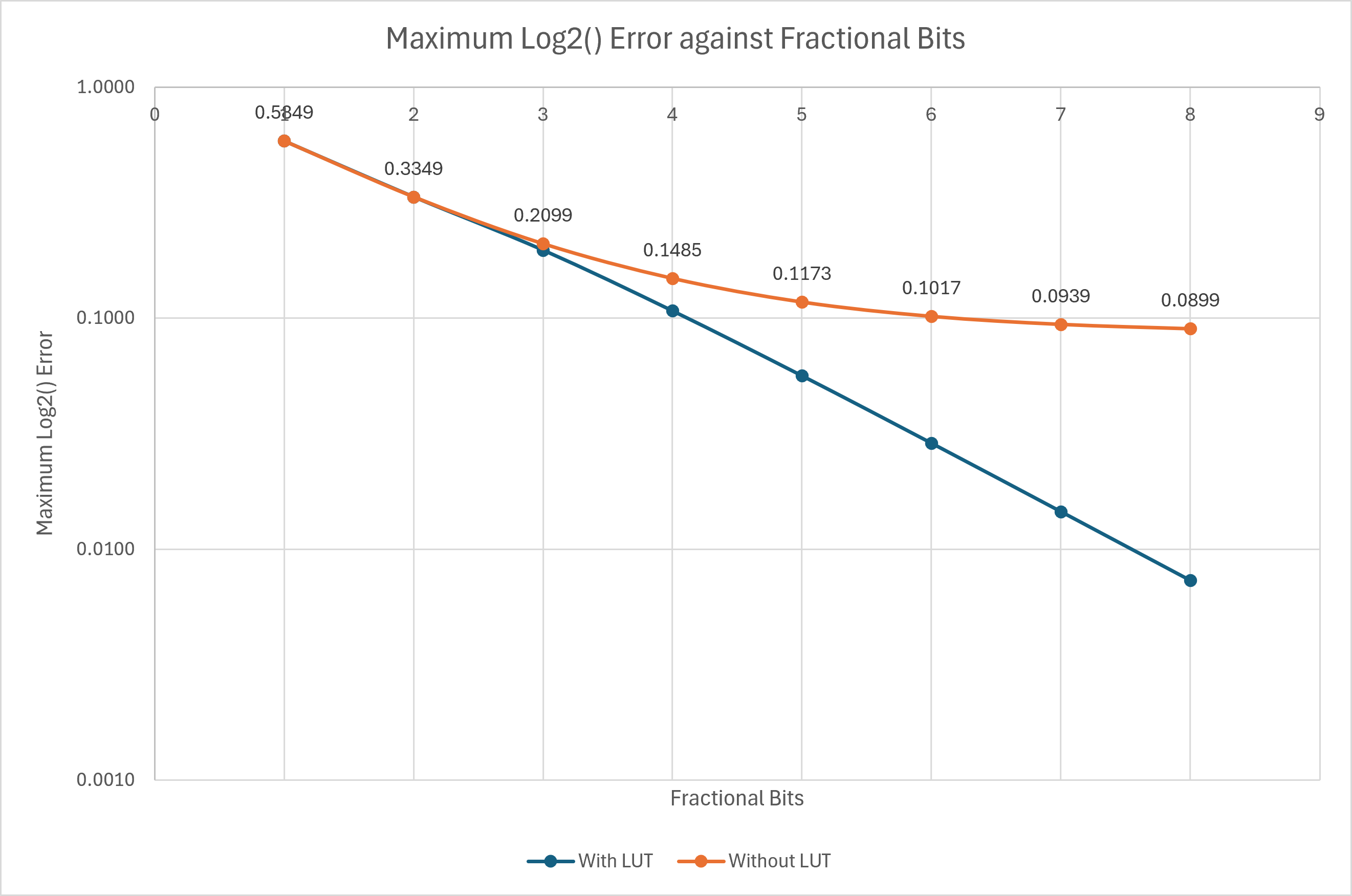
The lookup table above illustrates how the LUT's output value is very nearly the same as the LUT's input value. This means for a coarser result, the LUT can be omitted, hence the use_lut_g generic in the VHDL code.
Results
All the results have used a linear inputs of 16-bits and only worried about changing the number of fractional bits. The out of context synthesis method has been used as described in Specifying Boundary Timing Constraints in Vivado.
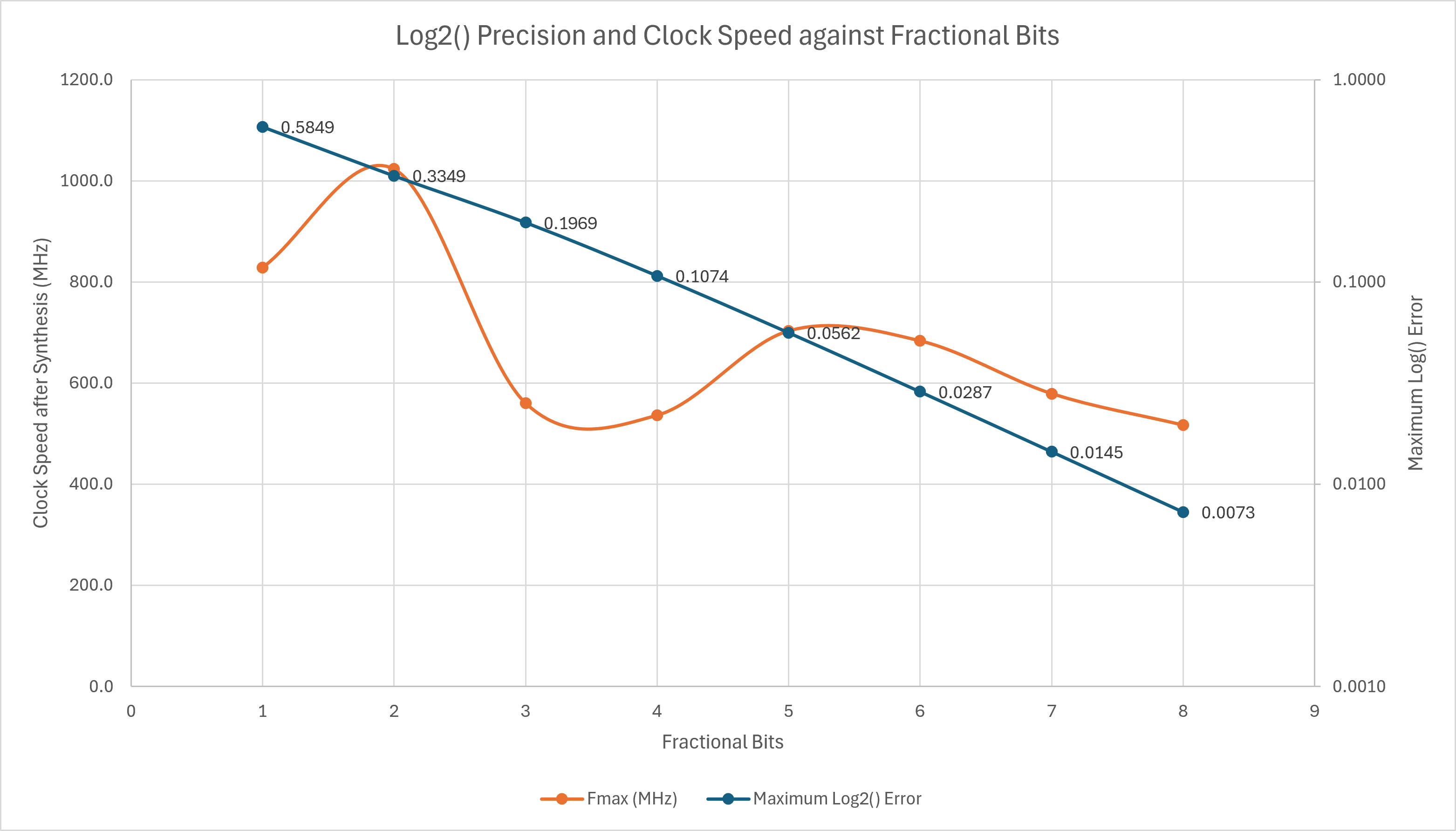
The results below show a favourable clock speed and accuracy without any pipelining. The Xilinx device used was xcku025-ffva1156-2-i and Vivado version 2023.2. The device was chosen from one of those usable in the free tier.
| Fractional bits | Maximum Log2() Error | Fmax (MHz) |
|---|---|---|
| 1 | 0.5849 | 828.5 |
| 2 | 0.3349 | 1023.5 |
| 3 | 0.1969 | 560.2 |
| 4 | 0.1074 | 536.2 |
| 5 | 0.0562 | 703.2 |
| 6 | 0.0287 | 683.5 |
| 7 | 0.0145 | 579.0 |
| 8 | 0.0073 | 516.8 |
As the design has a single stage of registers, the timing is calculated as if launched from a register on the inputs, and any timing after the output registers is ignored. Because of this, there may be some unrealistic estimates.
Each additional fractional bit might be assumed to reduce the output error by a half in line with the resolution of the additional fraction that can now be added to the output. More precisely, using linear regression on the log2(output), the output error ratio for one more fractional bit, f, is \({error(f) \over error(f+1)} = 0.533\) rather than 0.5, hence not quite halving with each bit.
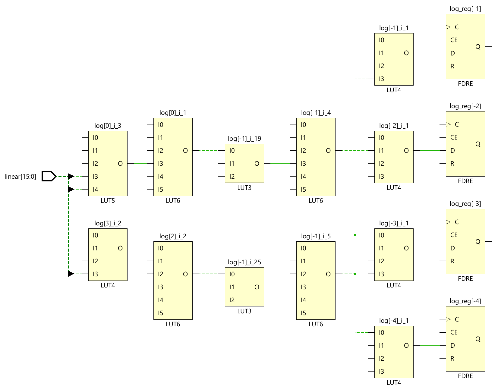
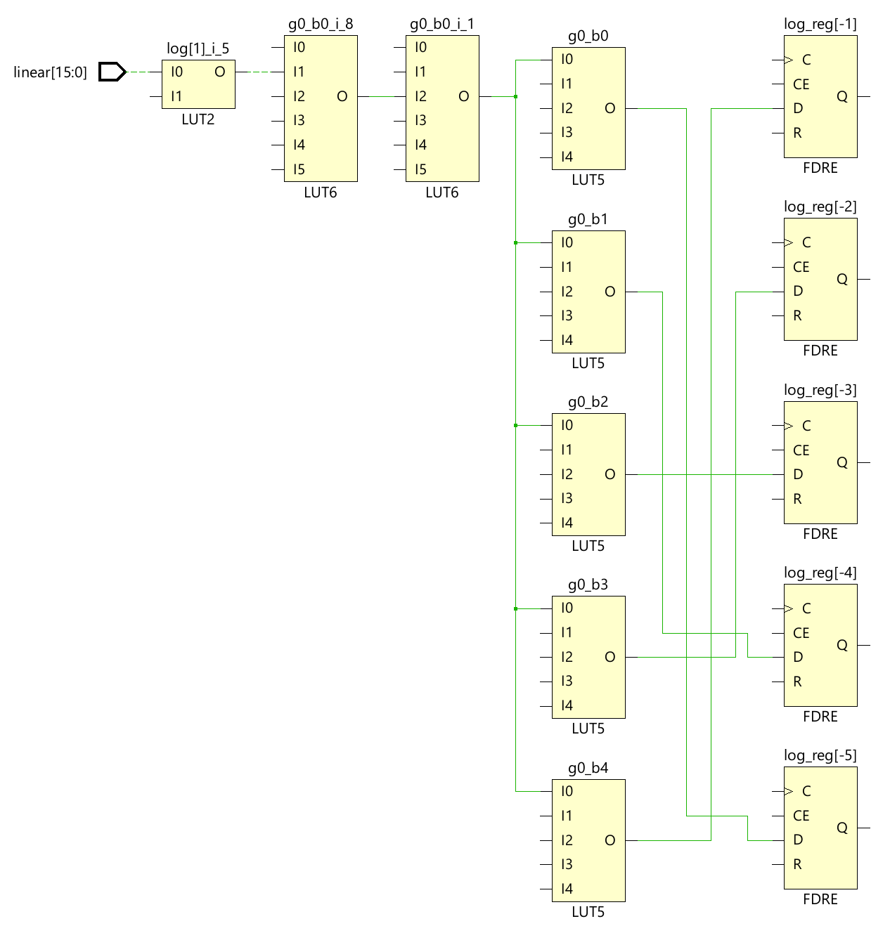
The cause of the poor performance of the 4 fractional bits clock speed over the 5 fractional bits is illustrated above. The lookup table has been realised as logic rather than a ROM, and the depth of the logic to the fractional bits is deeper for 4 over 5 factional bits. This looks like bad luck, the logic mapping was just more favourable in the former case. A similar explanation can be given for the unexpectedly good result for 2 fractional bits.
Optional Lookup Table
Taking away the lookup table gives synthesis results 828.5 - 1023.5 MHz over the range of fraction bit sizes in the table below (1-8). Whilst the error grows with fraction bits, the application, e.g. plotting a real-time spectrogram only for consumption by the human eye, may mean the error remains undetected, and the clock speed improvement may be more important.
| Fractional bits | Error with LUT | Error without LUT | Improvement in error |
|---|---|---|---|
| 1 | 58.5% | 58.5% | 0.0% |
| 2 | 33.5% | 33.5% | 0.0% |
| 3 | 19.7% | 21.0% | 1.3% |
| 4 | 10.7% | 14.9% | 4.1% |
| 5 | 5.6% | 11.7% | 6.1% |
| 6 | 2.9% | 10.2% | 7.3% |
| 7 | 1.5% | 9.4% | 7.9% |
| 8 | 0.7% | 9.0% | 8.3% |
AXI-Stream Pipeline
library ieee;
  use ieee.std_logic_1164.all;
  use ieee.fixed_pkg.all;
library local;

entity axis_quick_log2 is
  generic(
    data_width_g : positive := 16;
    frac_width_g : positive := 4
  );
  port (
    clk         : in  std_logic;
    s_axi_data  : in  std_logic_vector(data_width_g-1 downto 0); -- linear
    s_axi_valid : in  std_logic;
    s_axi_ready : out std_logic;
    -- Should probably be std_logic_vector, but the meaning is lost.
    -- Convert as you see fit.
    m_axi_data  : out ufixed(local.math_pkg.ceil_log(data_width_g, 2)-1 downto -frac_width_g) := (others => '0'); -- log
    m_axi_valid : out std_logic                                                               := '0';
    m_axi_ready : in  std_logic
  );
end entity;


library ieee;
  use ieee.numeric_std_unsigned.all;

architecture rtl of axis_quick_log2 is

  type lut_t is array (0 to 2**frac_width_g-1) of std_logic_vector(frac_width_g-1 downto 0);

  function log2_lut return lut_t is
    use ieee.math_real.log2;
    use ieee.math_real.round;
    variable ret : lut_t;
  begin
    for i in lut_t'range loop
      ret(i) := to_slv(
        integer(round(real(2**frac_width_g) * log2(real(1.0 + real(i)/real(2**frac_width_g))))),
        ret(i)'length
      );
    end loop;
    return ret;
  end function;

  constant log2_frac_lut_c : lut_t := log2_lut;

  function get_msb_pos(val : std_logic_vector) return integer is
  begin
    for i in val'range loop
      if val(i) = '1' then
        return i;
      end if;
    end loop;
    return 0;
  end function;

  signal valid_reg   : std_logic_vector(3 downto 1)              := (others => '0');
  signal ready_stage : std_logic_vector(3 downto 0)              := (others => '0');
  signal linear      : std_logic_vector(data_width_g-1 downto 0) := (others => '0');
  signal msb_idx     : integer range 0 to data_width_g-1         := 0;
  signal msb_idx_d1  : integer range 0 to data_width_g-1         := 0;
  signal msb_idx_d2  : integer range 0 to data_width_g-1         := 0;
  signal mantissa    : std_logic_vector(frac_width_g-1 downto 0) := (others => '0');
  signal fraction    : std_logic_vector(frac_width_g-1 downto 0) := (others => '0');

begin

  process(clk)
  begin
    if rising_edge(clk) then
      if ready_stage(3) = '1' then
        -- Find MSB position (Integer part)
        msb_idx      <= get_msb_pos(s_axi_data);
        linear       <= s_axi_data;
        valid_reg(3) <= s_axi_valid;
      end if;

      if ready_stage(2) = '1' then
        -- Extract fractional bits directly following the leading '1'
        -- Handles boundary cases where remaining bits are fewer than frac_width_g
        mantissa <= (others => '0');
        for j in 0 to frac_width_g-1 loop
          if (msb_idx - 1 - j) >= 0 then
            mantissa(frac_width_g - 1 - j) <= linear(msb_idx - 1 - j); -- XXX s_axi_data delayed by one cycle
          else
            mantissa(frac_width_g - 1 - j) <= '0';
          end if;
        end loop;
        valid_reg(2) <= valid_reg(3);
        msb_idx_d1   <= msb_idx;
      end if;

      if ready_stage(1) = '1' then
        -- Look up fractional bits
        fraction <= log2_frac_lut_c(to_integer(mantissa));
        valid_reg(1) <= valid_reg(2);
        msb_idx_d2   <= msb_idx_d1;
      end if;

      if ready_stage(0) = '1' then
        -- Combined 8-bit result in unsigned fixed point Qm.f format where:
        --  * m = log2(data_width_g)-1
        --  * f = frac_width_g
        m_axi_data  <= to_ufixed(to_slv(msb_idx_d2, local.math_pkg.ceil_log(data_width_g, 2)) & fraction, m_axi_data);
        m_axi_valid <= valid_reg(1);
      end if;

    end if;
  end process;

  ready_gen : for i in 3 downto 1 generate
    ready_stage(i) <= ready_stage(i-1) or not valid_reg(i);
  end generate;

  ready_stage(0) <= m_axi_ready or not m_axi_valid;
  s_axi_ready    <= ready_stage(ready_stage'high);

end architecture;
| Fractional bits | Unpipelined with LUT Fmax (MHz) | Unpipelined without LUT Fmax (MHz) | Pipelined Fmax (MHz) |
|---|---|---|---|
| 1 | 828.5 | 828.5 | 804.5 |
| 2 | 1023.5 | 1023.5 | 804.5 |
| 3 | 560.2 | 988.1 | 804.5 |
| 4 | 536.2 | 951.5 | 804.5 |
| 5 | 703.2 | 979.4 | 804.5 |
| 6 | 683.5 | 951.5 | 804.5 |
| 7 | 579.0 | 951.5 | 801.3 |
| 8 | 516.8 | 951.5 | 699.3 |
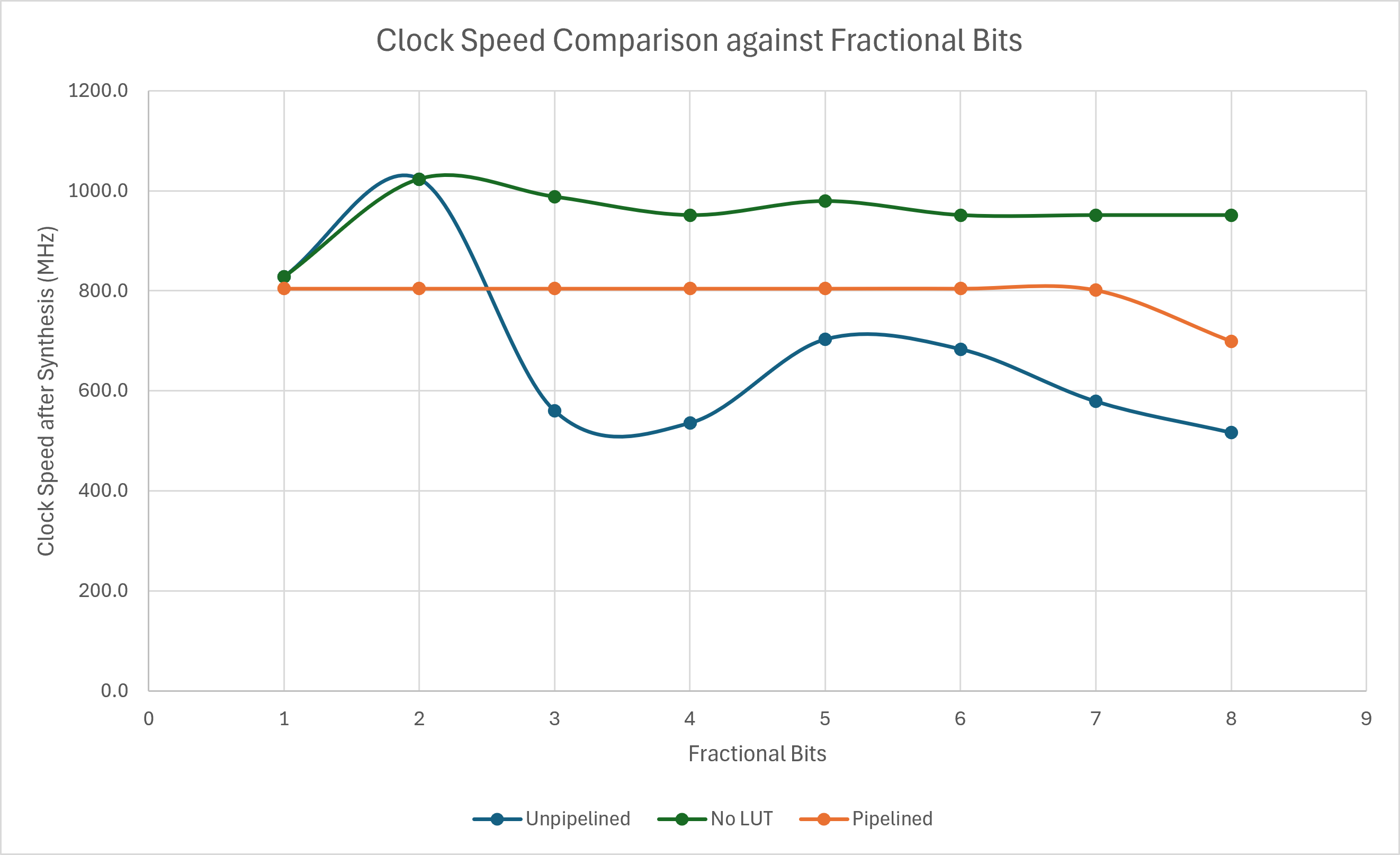
Above are the results for the same design with a 4-stage AXI-Stream Pipeline, one for each step in the calculation. The number of stages might yet be optimised based on synthesis timing. The tready line is unregistered in this implementation which follows the pattern used in AXI-Stream shift register.
Conclusions
Without the lookup table, whilst the error grows with fraction bits, the application, e.g. plotting a real-time spectrogram, may mean the error remains undetected, and the clock speed improvement may be more important. The pipelined implementation gives consistent and believable results in a practical design.
References
- Github Source Code
- DSP Trick: Quick-and-Dirty Logarithms by Ray Andraka
- FPGA Quick-and-Dirty Logarithms YouTube explanation by Adaptive Design
- Fixed point logarithm to base 2