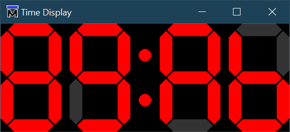
I recall many decades ago a Doulos training course where a seven-segment display was used as a VHDL exercise, and their test bench magic could drive a graphical display without which the exercise was dry and lifeless. Here's a demonstration of how to set that display up, using retro time display as an example. There's a simple VHDL "device under test" which is purely combinatorial logic, replicating a seven-segment display decoder once for each of four digits. In order to prevent the test bench running away to completion without seeing the display update, the TCL includes a stop statement, so run -all is required for the next update.
VHDL
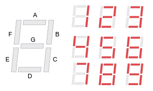
If you were deriving the logic manually you would follow a reference like 7-Segment HEX decoder. We're getting the synthesis tool to work that out for us, hence we just describe the outcome we want in VHDL.

library ieee;
  use ieee.std_logic_1164.all;

entity sevseg_display is
  port(
    digit : in  integer range 0 to 15;
    disp  : out std_logic_vector(6 downto 0)
  );
end entity;

architecture rtl of sevseg_display is
begin

  process(digit)
  begin
    case digit is --         "abcdefg"
      when  0     => disp <= "1111110";
      when  1     => disp <= "0110000";
      when  2     => disp <= "1101101";
      when  3     => disp <= "1111001";
      when  4     => disp <= "0110011";
      when  5     => disp <= "1011011";
      when  6     => disp <= "1011111";
      when  7     => disp <= "1110000";
      when  8     => disp <= "1111111";
      when  9     => disp <= "1111011";
      when 10     => disp <= "1110111"; -- A
      when 11     => disp <= "0011111"; -- b
      when 12     => disp <= "1001110"; -- C
      when 13     => disp <= "0111101"; -- d
      when 14     => disp <= "1001111"; -- E
      when 15     => disp <= "1000111"; -- F
      when others => disp <= "0000000";
    end case;
  end process;

end architecture;
Next we scale up from one to four digits, here I'm making the most of VHDL being strongly typed and constraining the integer values passing to only those the display decoder can render, and limiting the array length to 4 values.
library ieee;
  use ieee.std_logic_1164.all;

package sevseg_pkg is

  type digits_t    is array (0 to 3) of integer range 0 to 15;
  type time_disp_t is array (0 to 3) of std_logic_vector(6 downto 0);

end package;
entity time_display is
  port(
    digit : in  work.sevseg_pkg.digits_t;
    disp  : out work.sevseg_pkg.time_disp_t
  );
end entity;

architecture rtl of time_display is
begin

  gd : for i in digit'range generate

    sevseg_display_i : entity work.sevseg_display
      port map (
        digit => digit(i),
        disp  => disp(i)
      );

  end generate;

end architecture;
Finally a display driver using some rolling values in the range 0x0-0xF.
entity test_time_display is
end entity;

library ieee;
  use ieee.std_logic_1164.all;
library local;
  use local.testbench_pkg.all;

architecture rtl of test_time_display is

  signal clk   : std_logic := '0';
  signal digit : work.sevseg_pkg.digits_t;
  signal disp  : work.sevseg_pkg.time_disp_t;

begin

  clkgen : clock(clk, 10 ns);

  comp_time_display : entity work.time_display
    port map (
      digit => digit,
      disp  => disp
    );

  process
  begin
    digit <= (0, 1, 2, 3);
    wait_nr_ticks(clk, 1);

    for i in 0 to 15 loop
      digit <= (
        (digit(0)+1) mod 16,
        (digit(1)+1) mod 16,
        (digit(2)+1) mod 16,
        (digit(3)+1) mod 16
      );
      wait_nr_ticks(clk, 1);
    end loop;

    stop_clocks;
    wait;
  end process;

end architecture;
Part of the simulation which has been stopped just as the display has been updated to display "89Ab".

TCL
So this is the main point of the article, how to create the graphical dashboard to display the time. The work is split into parts as follows:
- Draw individual segments as a filled polygon in both horizonal and vertical orientations.
- Create a digit display with seven segments in it that can either be illuminated or off (two differen colours).
- Replicate the digit four times with a separator (:).
proc hseg {can w h {col #f00} {ox 0} {oy 0}} {
  $can create polygon \
    [expr      $h/2 + $ox]                   $oy  \
    [expr $w - $h/2 + $ox]                   $oy  \
    [expr $w        + $ox] [expr      $h/2 + $oy] \
    [expr $w - $h/2 + $ox] [expr $h        + $oy] \
    [expr      $h/2 + $ox] [expr $h        + $oy] \
                      $ox  [expr      $h/2 + $oy] \
    -outline $col -fill $col
}

proc vseg {can w h {col #f00} {ox 0} {oy 0}} {
  $can create polygon \
                      $ox  [expr      $w/2 + $oy] \
                      $ox  [expr $h - $w/2 + $oy] \
    [expr      $w/2 + $ox] [expr $h        + $oy] \
    [expr $w        + $ox] [expr $h - $w/2 + $oy] \
    [expr $w        + $ox] [expr      $w/2 + $oy] \
    [expr      $w/2 + $ox]                   $oy  \
    -outline $col -fill $col
}

#
#      a
#    #####
#   #     #
# f #     # b
#   #  g  #
#    #####
#   #     #
# e #     # c
#   #  d  #
#    #####
#
#                    0123456
#                    abcdefg
proc sevseg {can {b "0000000"} {w 20} {h 60} {g 2} {ox 0} {oy 0}} {
  global on off
  if {[string length $b] != 7} {
    error "Seven segment displays need precisely 7 bits."
  }
  # a
  if {[expr [string index $b 0] == "1"]} {
    hseg $can $h $w $on  [expr $w/2 + $g   + $ox]                          $oy
  } {
    hseg $can $h $w $off [expr $w/2 + $g   + $ox]                          $oy
  }
  # g
  if {[expr [string index $b 6] == "1"]} {
    hseg $can $h $w $on  [expr $w/2 + $g   + $ox] [expr $h        + $g*2 + $oy]
  } {
    hseg $can $h $w $off [expr $w/2 + $g   + $ox] [expr $h        + $g*2 + $oy]
  }
  # d
  if {[expr [string index $b 3] == "1"]} {
    hseg $can $h $w $on  [expr $w/2 + $g   + $ox] [expr $h*2      + $g*4 + $oy]
  } {
    hseg $can $h $w $off [expr $w/2 + $g   + $ox] [expr $h*2      + $g*4 + $oy]
  }
  # f
  if {[expr [string index $b 5] == "1"]} {
    vseg $can $w $h $on                      $ox  [expr      $w/2 + $g   + $oy]
  } {
    vseg $can $w $h $off                     $ox  [expr      $w/2 + $g   + $oy]
  }
  # b
  if {[expr [string index $b 1] == "1"]} {
    vseg $can $w $h $on  [expr $h   + $g*2 + $ox] [expr      $w/2 + $g   + $oy]
  } {
    vseg $can $w $h $off [expr $h   + $g*2 + $ox] [expr      $w/2 + $g   + $oy]
  }
  # e
  if {[expr [string index $b 4] == "1"]} {
    vseg $can $w $h $on                      $ox  [expr $h + $w/2 + $g*3 + $oy]
  } {
    vseg $can $w $h $off                     $ox  [expr $h + $w/2 + $g*3 + $oy]
  }
  # c
  if {[expr [string index $b 2] == "1"]} {
    vseg $can $w $h $on  [expr $h   + $g*2 + $ox] [expr $h + $w/2 + $g*3 + $oy]
  } {
    vseg $can $w $h $off [expr $h   + $g*2 + $ox] [expr $h + $w/2 + $g*3 + $oy]
  }
}

proc display {can s0 s1 s2 s3} {
  global width height gap space on winheight winwidth
  set dw [expr $height + $width + $gap*2]
  destroy $can
  canvas $can -width $winwidth -height $winheight -background #000
  sevseg $can $s0 $width $height $gap 0
  sevseg $can $s1 $width $height $gap [expr $dw + $space]
  # Central pair of dots, ':'
  $can create oval \
    [expr $dw*2 + $space*2         ] [expr $height  /2 +          $gap*2] \
    [expr $dw*2 + $space*2 + $width] [expr $height  /2 + $width + $gap*2] \
    -outline $on -fill $on
  $can create oval \
    [expr $dw*2 + $space*2         ] [expr $height*3/2 +          $gap*2] \
    [expr $dw*2 + $space*2 + $width] [expr $height*3/2 + $width + $gap*2] \
    -outline $on -fill $on
  sevseg $can $s2 $width $height $gap [expr $dw*2 + $space*3 + $width]
  sevseg $can $s3 $width $height $gap [expr $dw*3 + $space*4 + $width]
  pack $can
}

# Global variables
set on       #f00
set off      #333
set width      16
set height     60
set gap         2
set space      12
set winwidth  [expr ($height   + $width + $gap*2 + $space)*4 + $width + 1]
set winheight [expr  $height*2 + $width + $gap*4                      + 1]

destroy .sevseg
toplevel .sevseg
# Four seven segment displays for the time
display .sevseg.time "0000000" "0000000" "0000000" "0000000"
wm title .sevseg "Time Display"
wm geometry .sevseg ${winwidth}x${winheight}+100+100
Now we need to set up a trigger so that whenever the time changes, the display is updated. For this we need to trigger the display update each time there's an event on the decoded clock display. We will also issue a stop command so that we can see each update and then continue the simulation with run -all.
# Setup the trigger to update the display
set monitor {/test_time_display/disp }
when -label updateTime "${monitor}'event" {
  display .sevseg.time \
    [examine -radix bin "sim:${monitor}(0)"] \
    [examine -radix bin "sim:${monitor}(1)"] \
    [examine -radix bin "sim:${monitor}(2)"] \
    [examine -radix bin "sim:${monitor}(3)"]
  # Don't let the sim run away, we won't see the display update
  stop
}
Follow these steps to load and execute the simulation.
ModelSim> cd {path\to\ModelSim\projects\tcltk}
# reading modelsim.ini
ModelSim> vsim work.test_time_display
# vsim work.test_time_display
# Start time: 09:38:22 on Sep 19,2022
# Loading std.standard
# Loading std.textio(body)
# Loading ieee.std_logic_1164(body)
# Loading ieee.math_real(body)
# Loading local.testbench_pkg(body)
# Loading work.sevseg_pkg
# Loading work.test_time_display(rtl)
# Loading work.time_display(rtl)
# Loading work.sevseg_display(rtl)

VSIM 5> source {path\to\sevseg_display.tcl}
VSIM 6> run -all
And finally, we get a sequence, "0123", "1234", "2345" .. "F012".

Conclusions
It's a fun thing to do, but not exactly self-checking for use with continuous integration. A lot of effort can be spent getting the graphical display to look good.
It is also worth noting that you can update a VHDL signal from TCL using the
forcecommand:force -deposit <signal_name> <value></value></signal_name>This means that bidirectional communication between TCL and VHDL is possible.